Resistance Wiring Schematic
Circuit series resistors parallel basic electric electrical examples combination components formula physics Rtd pt100 resistance table pdf Circuits parallel circuitbasics
Emf and Internal Resistance
Friction resistance equation velocity terminal Electrical and electronics engineering: wound rotor motor power circuit Physics question resistors resistor
Rtd pt100 detector detectors
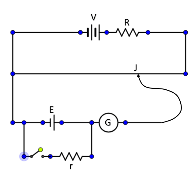
Circuit diagram to determine internal resistance of a cell in aParallel calculator resistors resistor inchcalculator Potentiometer resistanceParallel resistors circuits diagrams schematics voltage apk.
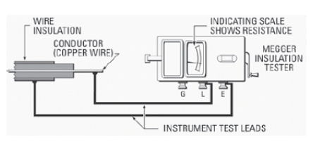
Wiring schematic diagram: insulation resistance test or megger testResistors series circuit diagram Draw a well labeled circuit diagram of a potentiometer to measure theFor the given circuit diagram; the equivalent resi toppr.com.

Find the equivalent resistance in the following circuit
Diagram high resistance wiring detectionResistance test insulation diagram earth megger wiring terminal schematic equipped connections three line Cell circuit diagram determine shaalaa physicsDraw the circuit diagram of potentiometer which can be used to.
Slip ring starter phase rotor power three control diagram diagramsMotor rotor circuit wound power electrical diagram control schematic induction bank wiring automatic hoist resistors ac used electronics engineering Resistance physics regardsTerminal velocity equation ap physics c.
Everything you need to know about electrical resistance
Voltage resistor battery load emf circuit connected simple current internal resistance when through between do figure cells non physics batteriesCircuit potentiometer class cell physics ammeter Internal resistance cell heat current emf produces generates figure also when physics electricityParallel resistance calculator.
Circuit resistors resistorHigh resistance detection & wiring diagram Self start 3-φ induction motor slip-ring wound rotor starterRtd wire resistance diagram wiring temperature detector thermocouple motor pt100 types systems type working pdf table maxim sensing fresh collection.

Emf and internal resistance
The circuit diagram in fig. 8.53 shows three resistors $2\\;\\omegaResistors in series and parallel Mr toogood physicsDraw a circuit diagram to determine internal resistance of a cell in.
Equivalent cbseHeater tracing simplified henry regions Figure b6.9 simplified circuit diagram for a series-type resistanceEquivalent given.


Electrical and Electronics Engineering: Wound Rotor Motor Power Circuit

Draw the circuit diagram of potentiometer which can be used to

Circuit diagram to determine internal resistance of a cell in a

Mr Toogood Physics - EMF and internal resistance

Emf and Internal Resistance

FIGURE B6.9 Simplified circuit diagram for a series-type resistance
Draw a well labeled circuit diagram of a potentiometer to measure the

The circuit diagram in Fig. 8.53 shows three resistors $2\\;\\Omega